Week 9: Output Devices
For this week’s assignment, I decided to focus on my final project. Since I’m still not sure about the output of my final project (!) – It can be either a Servo Motor or RGB LED – I decided to try both of these outputs. I bought a Servo from Radioshak, and grabbed a couple of RGB LEDs from Archshop and started playing.
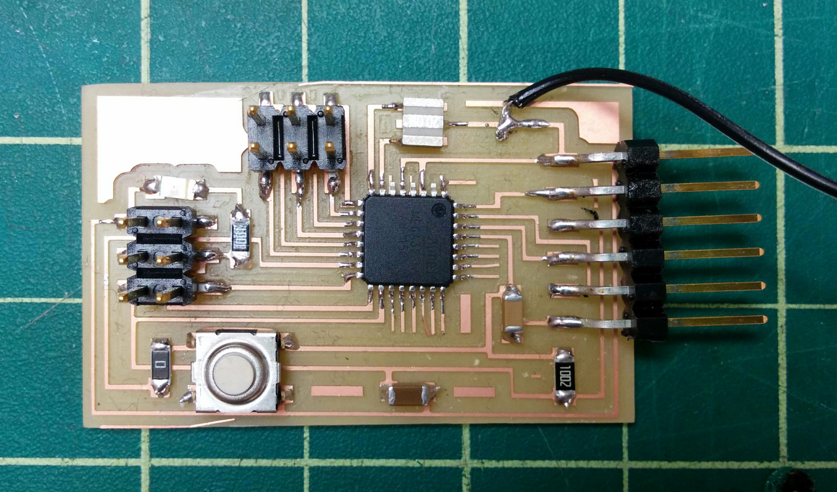
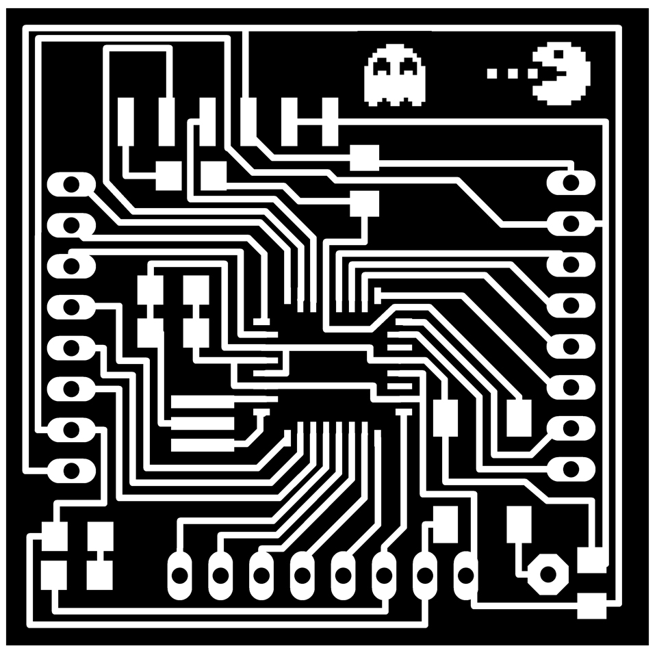
There are some circuit design samples in class’s website for each of the output devices, but I decided to make my own Fabduino and attach the output devices to it, so that I can use my Fabduino for the next week’s assignment (Input Devices) as well as my final project.
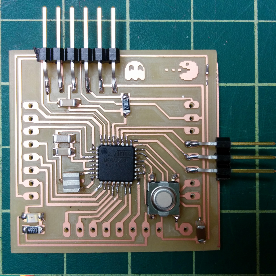
Since I’m still not completely comfortable with electronics design, and since I’m still not sure about the input and output devices for my final project, I decided to make the Fabduino without any changes, and instead fabricate tiny circuits just to attach the output devices to the Arduino. While I was making Fabduino, I came across the FabKit which had more traces for output headers – I went ahead and fabricated it too. I also ordered some female headers – which hasn’t still arrived – to solder to my Fabkit and make my own Arduino.
RGB LED:
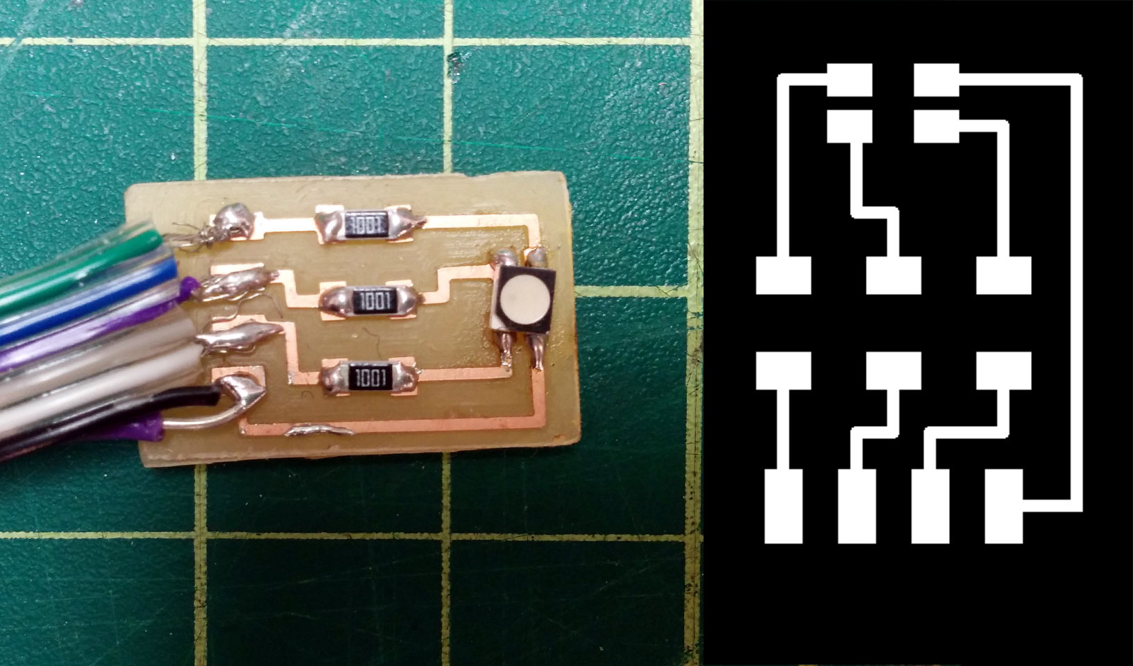
From what I’ve learned from circuit’s samples on class’s website, I realized that my RGB LED needs to be attached to 3 pins on microcontroller and VCC. Also, I needed to use resistors in order to regulate the current for the LED. With these in mind, I went ahead and designed a tiny circuit for my LED, and I included a header to attach 3 the LED to 3 pins of the microcontroller. I used a jumper wire to attach the VCC of LED circuit to VCC of the Fabduino. This is the result :
Servo Motor:
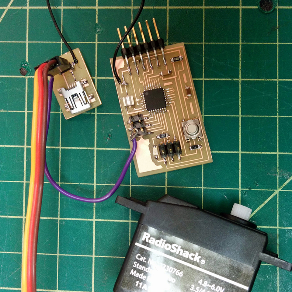
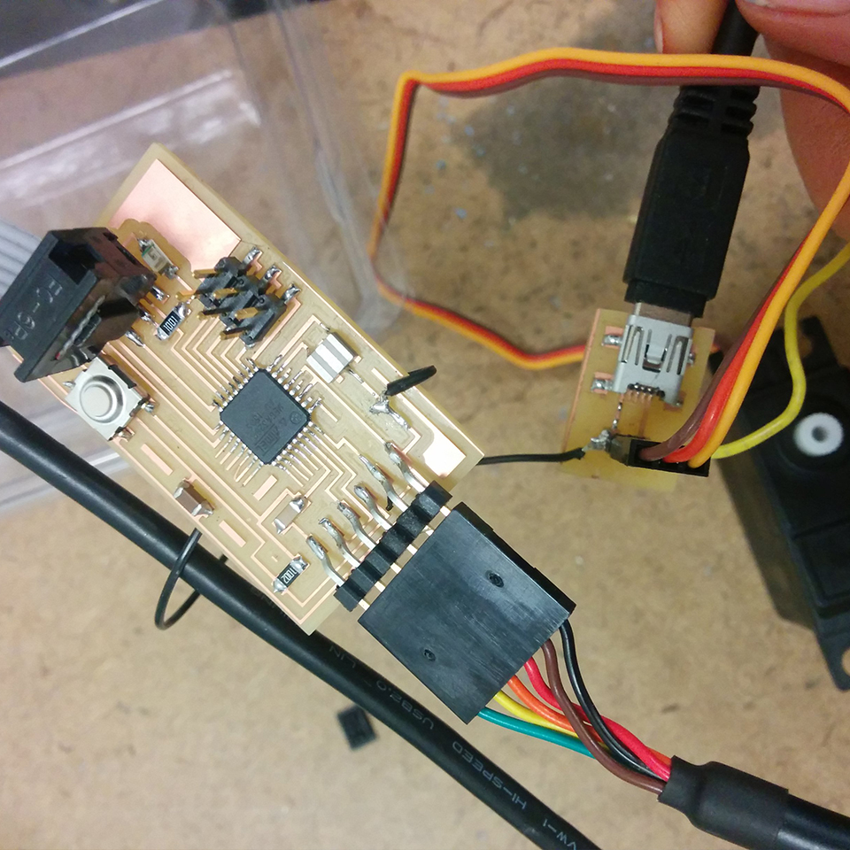
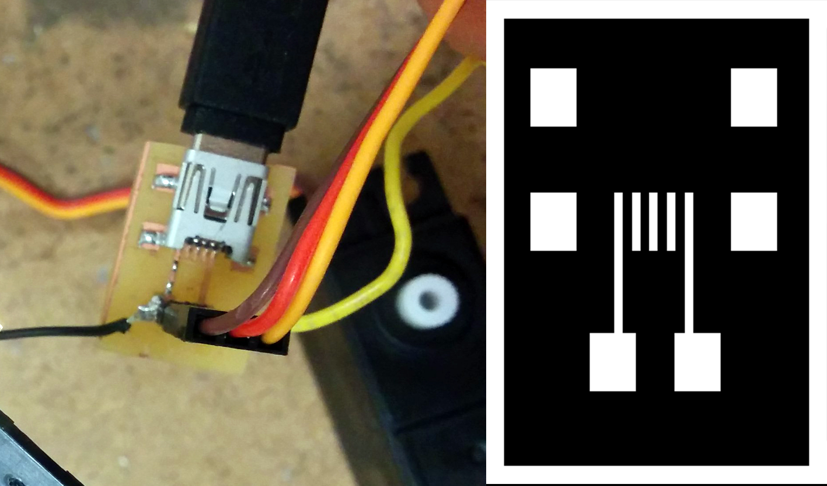
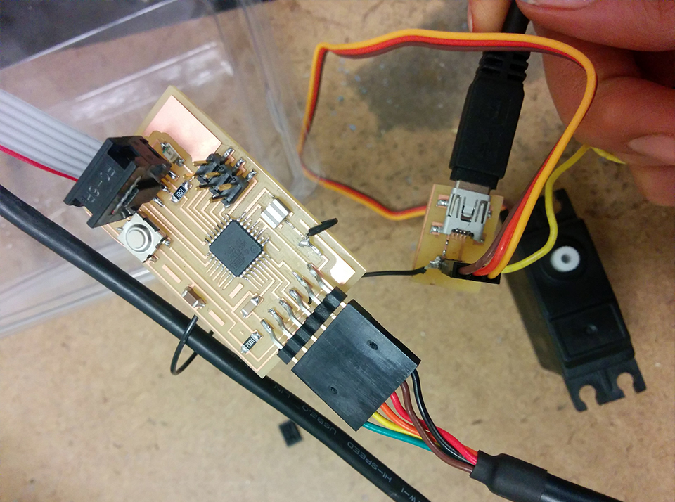
Servo should be connected to VCC, GND and a pin on microcontroller. Servo should get it’s power from a source other that Fabduino – such as a battery. Thus, the VCC of servo is different from VCC of Fabduino. However, both GNDs should be attached to each other. Since I didn’t have a battery (!) I decided to get the power for the Servo from my laptop via USB. I designed another tiny circuit just with a USB outlet and two male headers that could be attached to Servo. The GND is attached to Fabduino’s GND via jumper wire, and servo is attached to pin 5 of Fabduino with another jumper wire.
Programming my board … Failed
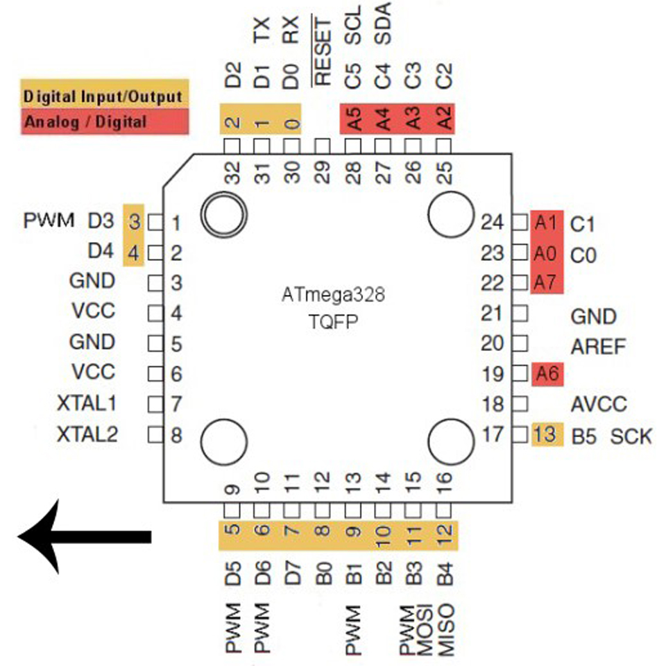
After doing all these work, I decided to load the simple programs that I wrote in Arduino to the boards – but I faced a major problem. Apparently, Arduino software is not very friendly with windows – at least the way we want to use it which is adding boards other that Arduino’s own boards. I still haven’t been able to load my board and controller – MEGA328P – in the Arduino software. I’ve decided to install Ubunto on my laptop … maybe that would work. This page will definitely be updated!
Servo should be connected to VCC, GND and a pin on microcontroller. Servo should get it’s power from a source other that Fabduino – such as a battery. Thus, the VCC of servo is different from VCC of Fabduino. However, both GNDs should be attached to each other. Since I didn’t have a battery (!) I decided to get the power for the Servo from my laptop via USB. I designed another tiny circuit just with a USB outlet and two male headers that could be attached to Servo. The GND is attached to Fabduino’s GND via jumper wire, and servo is attached to pin 5 of Fabduino with another jumper wire.
Programming my board … Failed
After doing all these work, I decided to load the simple programs that I wrote in Arduino to the boards – but I faced a major problem. Apparently, Arduino software is not very friendly with windows – at least the way we want to use it which is adding boards other that Arduino’s own boards. I still haven’t been able to load my board and controller – MEGA328P – in the Arduino software. I’ve decided to install Ubunto on my laptop … maybe that would work. This page will definitely be updated!